Quick reference for the ESP32
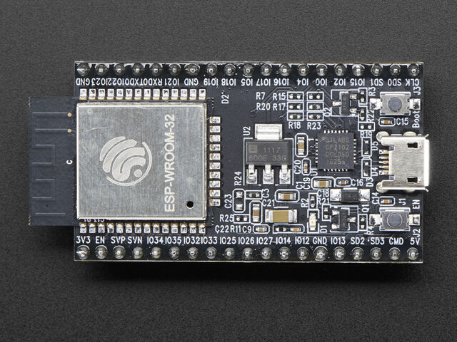
The Espressif ESP32 Development Board (image attribution: Adafruit).
Below is a quick reference for ESP32-based boards. If it is your first time working with this board it may be useful to get an overview of the microcontroller:
Installing MicroPython
See the corresponding section of tutorial: Getting started with MicroPython on the ESP32. It also includes a troubleshooting subsection.
General board control
The MicroPython REPL is on UART0 (GPIO1=TX, GPIO3=RX) at baudrate 115200. Tab-completion is useful to find out what methods an object has. Paste mode (ctrl-E) is useful to paste a large slab of Python code into the REPL.
The machine module:
import machine

machine.freq()          # get the current frequency of the CPU
machine.freq(240000000) # set the CPU frequency to 240 MHz
The esp module:
import esp

esp.osdebug(None)       # turn off vendor O/S debugging messages
esp.osdebug(0)          # redirect vendor O/S debugging messages to UART(0)

# low level methods to interact with flash storage
esp.flash_size()
esp.flash_user_start()
esp.flash_erase(sector_no)
esp.flash_write(byte_offset, buffer)
esp.flash_read(byte_offset, buffer)
The esp32 module:
import esp32

esp32.hall_sensor()     # read the internal hall sensor
esp32.raw_temperature() # read the internal temperature of the MCU, in Farenheit
esp32.ULP()             # access to the Ultra-Low-Power Co-processor
Note that the temperature sensor in the ESP32 will typically read higher than ambient due to the IC getting warm while it runs. This effect can be minimised by reading the temperature sensor immediately after waking up from sleep.
Networking
The network module:
import network

wlan = network.WLAN(network.STA_IF) # create station interface
wlan.active(True)       # activate the interface
wlan.scan()             # scan for access points
wlan.isconnected()      # check if the station is connected to an AP
wlan.connect('essid', 'password') # connect to an AP
wlan.config('mac')      # get the interface's MAC adddress
wlan.ifconfig()         # get the interface's IP/netmask/gw/DNS addresses

ap = network.WLAN(network.AP_IF) # create access-point interface
ap.config(essid='ESP-AP') # set the ESSID of the access point
ap.active(True)         # activate the interface
A useful function for connecting to your local WiFi network is:
def do_connect():
    import network
    wlan = network.WLAN(network.STA_IF)
    wlan.active(True)
    if not wlan.isconnected():
        print('connecting to network...')
        wlan.connect('essid', 'password')
        while not wlan.isconnected():
            pass
    print('network config:', wlan.ifconfig())
Once the network is established the socket module can be used
to create and use TCP/UDP sockets as usual, and the urequests module for
convenient HTTP requests.
Delay and timing
Use the time module:
import time

time.sleep(1)           # sleep for 1 second
time.sleep_ms(500)      # sleep for 500 milliseconds
time.sleep_us(10)       # sleep for 10 microseconds
start = time.ticks_ms() # get millisecond counter
delta = time.ticks_diff(time.ticks_ms(), start) # compute time difference
Timers
Virtual (RTOS-based) timers are supported. Use the machine.Timer class with timer ID of -1:
from machine import Timer

tim = Timer(-1)
tim.init(period=5000, mode=Timer.ONE_SHOT, callback=lambda t:print(1))
tim.init(period=2000, mode=Timer.PERIODIC, callback=lambda t:print(2))
The period is in milliseconds.
Pins and GPIO
Use the machine.Pin class:
from machine import Pin

p0 = Pin(0, Pin.OUT)    # create output pin on GPIO0
p0.on()                 # set pin to "on" (high) level
p0.off()                # set pin to "off" (low) level
p0.value(1)             # set pin to on/high

p2 = Pin(2, Pin.IN)     # create input pin on GPIO2
print(p2.value())       # get value, 0 or 1

p4 = Pin(4, Pin.IN, Pin.PULL_UP) # enable internal pull-up resistor
p5 = Pin(5, Pin.OUT, value=1) # set pin high on creation
Available Pins are from the following ranges (inclusive): 0-19, 21-23, 25-27, 32-39. These correspond to the actual GPIO pin numbers of ESP32 chip. Note that many end-user boards use their own adhoc pin numbering (marked e.g. D0, D1, …). For mapping between board logical pins and physical chip pins consult your board documentation.
Notes:
- Pins 1 and 3 are REPL UART TX and RX respectively
- Pins 6, 7, 8, 11, 16, and 17 are used for connecting the embedded flash, and are not recommended for other uses
- Pins 34-39 are input only, and also do not have internal pull-up resistors
PWM (pulse width modulation)
PWM can be enabled on all output-enabled pins. The base frequency can range from 1Hz to 40MHz but there is a tradeoff; as the base frequency increases the duty resolution decreases. See LED Control for more details.
Use the machine.PWM class:
from machine import Pin, PWM

pwm0 = PWM(Pin(0))      # create PWM object from a pin
pwm0.freq()             # get current frequency
pwm0.freq(1000)         # set frequency
pwm0.duty()             # get current duty cycle
pwm0.duty(200)          # set duty cycle
pwm0.deinit()           # turn off PWM on the pin

pwm2 = PWM(Pin(2), freq=20000, duty=512) # create and configure in one go
ADC (analog to digital conversion)
On the ESP32 ADC functionality is available on Pins 32-39. Note that, when using the default configuration, input voltages on the ADC pin must be between 0.0v and 1.0v (anything above 1.0v will just read as 4095). Attenuation must be applied in order to increase this usable voltage range.
Use the machine.ADC class:
from machine import ADC

adc = ADC(Pin(32))          # create ADC object on ADC pin
adc.read()                  # read value, 0-4095 across voltage range 0.0v - 1.0v

adc.atten(ADC.ATTN_11DB)    # set 11dB input attentuation (voltage range roughly 0.0v - 3.6v)
adc.width(ADC.WIDTH_9BIT)   # set 9 bit return values (returned range 0-511)
adc.read()                  # read value using the newly configured attenuation and width
ESP32 specific ADC class method reference:
-
ADC.atten(attenuation)¶ This method allows for the setting of the amount of attenuation on the input of the ADC. This allows for a wider possible input voltage range, at the cost of accuracy (the same number of bits now represents a wider range). The possible attenuation options are:
ADC.ATTN_0DB: 0dB attenuation, gives a maximum input voltage of 1.00v - this is the default configurationADC.ATTN_2_5DB: 2.5dB attenuation, gives a maximum input voltage of approximately 1.34vADC.ATTN_6DB: 6dB attenuation, gives a maximum input voltage of approximately 2.00vADC.ATTN_11DB: 11dB attenuation, gives a maximum input voltage of approximately 3.6v
Warning
Despite 11dB attenuation allowing for up to a 3.6v range, note that the absolute maximum voltage rating for the input pins is 3.6v, and so going near this boundary may be damaging to the IC!
-
ADC.width(width)¶ This method allows for the setting of the number of bits to be utilised and returned during ADC reads. Possible width options are:
ADC.WIDTH_9BIT: 9 bit dataADC.WIDTH_10BIT: 10 bit dataADC.WIDTH_11BIT: 11 bit dataADC.WIDTH_12BIT: 12 bit data - this is the default configuration
Software SPI bus
There are two SPI drivers. One is implemented in software (bit-banging) and works on all pins, and is accessed via the machine.SPI class:
from machine import Pin, SPI

# construct an SPI bus on the given pins
# polarity is the idle state of SCK
# phase=0 means sample on the first edge of SCK, phase=1 means the second
spi = SPI(baudrate=100000, polarity=1, phase=0, sck=Pin(0), mosi=Pin(2), miso=Pin(4))

spi.init(baudrate=200000) # set the baudrate

spi.read(10)            # read 10 bytes on MISO
spi.read(10, 0xff)      # read 10 bytes while outputing 0xff on MOSI

buf = bytearray(50)     # create a buffer
spi.readinto(buf)       # read into the given buffer (reads 50 bytes in this case)
spi.readinto(buf, 0xff) # read into the given buffer and output 0xff on MOSI

spi.write(b'12345')     # write 5 bytes on MOSI

buf = bytearray(4)      # create a buffer
spi.write_readinto(b'1234', buf) # write to MOSI and read from MISO into the buffer
spi.write_readinto(buf, buf) # write buf to MOSI and read MISO back into buf
Warning
Currently all of sck, mosi and miso must be specified when
initialising Software SPI.
Hardware SPI bus
There are two hardware SPI channels that allow faster (up to 80Mhz) transmission rates, but are only supported on a subset of pins.
| HSPI (id=1) | VSPI (id=2) | |
|---|---|---|
| sck | 14 | 18 |
| mosi | 13 | 23 |
| miso | 12 | 19 |
Hardware SPI has the same methods as Software SPI above:
from machine import Pin, SPI

hspi = SPI(1, 10000000, sck=Pin(14), mosi=Pin(13), miso=Pin(12))
vspi = SPI(2, baudrate=80000000, polarity=0, phase=0, bits=8, firstbit=0, sck=Pin(18), mosi=Pin(23), miso=Pin(19))
I2C bus
The I2C driver is implemented in software and works on all pins, and is accessed via the machine.I2C class:
from machine import Pin, I2C

# construct an I2C bus
i2c = I2C(scl=Pin(5), sda=Pin(4), freq=100000)

i2c.readfrom(0x3a, 4)   # read 4 bytes from slave device with address 0x3a
i2c.writeto(0x3a, '12') # write '12' to slave device with address 0x3a

buf = bytearray(10)     # create a buffer with 10 bytes
i2c.writeto(0x3a, buf)  # write the given buffer to the slave
Real time clock (RTC)
See machine.RTC
from machine import RTC

rtc = RTC()
rtc.datetime((2017, 8, 23, 1, 12, 48, 0, 0)) # set a specific date and time
rtc.datetime() # get date and time
Deep-sleep mode
The following code can be used to sleep, wake and check the reset cause:
import machine

# check if the device woke from a deep sleep
if machine.reset_cause() == machine.DEEPSLEEP_RESET:
    print('woke from a deep sleep')

# put the device to sleep for 10 seconds
machine.deepsleep(10000)
Notes:
- Calling
deepsleep()without an argument will put the device to sleep indefinitely - A software reset does not change the reset cause
OneWire driver
The OneWire driver is implemented in software and works on all pins:
from machine import Pin
import onewire

ow = onewire.OneWire(Pin(12)) # create a OneWire bus on GPIO12
ow.scan()               # return a list of devices on the bus
ow.reset()              # reset the bus
ow.readbyte()           # read a byte
ow.writebyte(0x12)      # write a byte on the bus
ow.write('123')         # write bytes on the bus
ow.select_rom(b'12345678') # select a specific device by its ROM code
There is a specific driver for DS18S20 and DS18B20 devices:
import time, ds18x20
ds = ds18x20.DS18X20(ow)
roms = ds.scan()
ds.convert_temp()
time.sleep_ms(750)
for rom in roms:
    print(ds.read_temp(rom))
Be sure to put a 4.7k pull-up resistor on the data line. Note that
the convert_temp() method must be called each time you want to
sample the temperature.
NeoPixel driver
Use the neopixel module:
from machine import Pin
from neopixel import NeoPixel

pin = Pin(0, Pin.OUT)   # set GPIO0 to output to drive NeoPixels
np = NeoPixel(pin, 8)   # create NeoPixel driver on GPIO0 for 8 pixels
np[0] = (255, 255, 255) # set the first pixel to white
np.write()              # write data to all pixels
r, g, b = np[0]         # get first pixel colour
For low-level driving of a NeoPixel:
import esp
esp.neopixel_write(pin, grb_buf, is800khz)
Warning
By default NeoPixel is configured to control the more popular 800kHz
units. It is possible to use alternative timing to control other (typically
400kHz) devices by passing timing=0 when constructing the
NeoPixel object.
Capacitive Touch
Use the TouchPad class in the machine module:
from machine import TouchPad, Pin

t = TouchPad(Pin(14))
t.read()              # Returns a smaller number when touched
TouchPad.read returns a value relative to the capacitive variation. Small numbers (typically in
the tens) are common when a pin is touched, larger numbers (above one thousand) when
no touch is present. However the values are relative and can vary depending on the board
and surrounding composition so some calibration may be required.
There are ten capacitive touch-enabled pins that can be used on the ESP32: 0, 2, 4, 12, 13
14, 15, 27, 32, 33. Trying to assign to any other pins will result in a ValueError.
Note that TouchPads can be used to wake an ESP32 from sleep:
import machine
from machine import TouchPad, Pin
import esp32

t = TouchPad(Pin(14))
t.config(500)               # configure the threshold at which the pin is considered touched
esp32.wake_on_touch(True)
machine.lightsleep()        # put the MCU to sleep until a touchpad is touched
For more details on touchpads refer to Espressif Touch Sensor.
DHT driver
The DHT driver is implemented in software and works on all pins:
import dht
import machine

d = dht.DHT11(machine.Pin(4))
d.measure()
d.temperature() # eg. 23 (°C)
d.humidity()    # eg. 41 (% RH)

d = dht.DHT22(machine.Pin(4))
d.measure()
d.temperature() # eg. 23.6 (°C)
d.humidity()    # eg. 41.3 (% RH)
WebREPL (web browser interactive prompt)
WebREPL (REPL over WebSockets, accessible via a web browser) is an experimental feature available in ESP32 port. Download web client from https://github.com/micropython/webrepl (hosted version available at http://micropython.org/webrepl), and configure it by executing:
import webrepl_setup
and following on-screen instructions. After reboot, it will be available for connection. If you disabled automatic start-up on boot, you may run configured daemon on demand using:
import webrepl
webrepl.start()

# or, start with a specific password
webrepl.start(password='mypass')
The WebREPL daemon listens on all active interfaces, which can be STA or AP. This allows you to connect to the ESP32 via a router (the STA interface) or directly when connected to its access point.
In addition to terminal/command prompt access, WebREPL also has provision
for file transfer (both upload and download). The web client has buttons for
the corresponding functions, or you can use the command-line client
webrepl_cli.py from the repository above.
See the MicroPython forum for other community-supported alternatives to transfer files to an ESP32 board.